Keywords: Ultrasonic scattering field; Directivity; Dynamic photoelastic technique; Cylindrical cavity
Dynamic photoelastic technique, whose physical basis is temporary birefringent effect, is an experimental method to investigate stress or stress waves. It was firstly used to study the stress fields, mainly static in solid structures, and extended to display ultrasonic waves in transparent solids. A series of investigations on scattering of ultrasonic waves in solid medium by the dynamic photoelastic visualization were also carried out. Results not only verified the conclusion of theoretical analyses, but also showed some new phenomena.
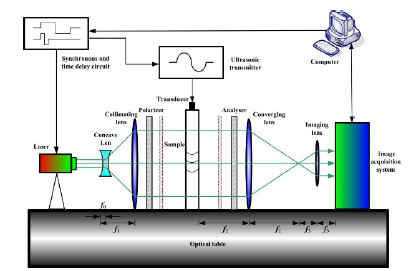
On the basis of the previous research, a new photoelastic visualization system has been developed with modern techniques (see Fig.1) by researchers from the Institute of Acoustics of the Chinese Academy of Sciences. In this new system, the light source is a pulsed laser, emitting a high intensity green light beam with very short duration (about 3.8ns). Trigger pulses are sent from an interface controller to laser and ultrasonic transducer, for their synchronization with each other.
The laser is triggered after a time delay, so the position of ultrasonic waves in sample can be changed to record the propagation and scattering process of various waves by varying the delay. In the end, the photographs taken by the image acquisition system are sent to a computer for further analysis.
As the image acquisition system takes the photoelastic photographs, the original photograph is encoded onto RGB (red-green-blue) color channels. Since the laser emits green light, only one green channel is used in the image analysis. There are 256 gray levels per pixel in the photograph, and the gray level reflects the quantity of illumination which is proportional to the output light intensity.
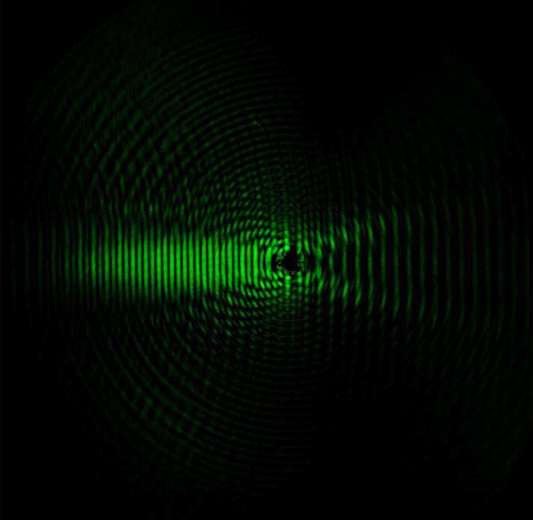
The ultrasonic wave, radiated by a piston-type transducer and later scattered by a cylindrical cavity, is studied by the photoelastic visualization system described above (see Fig.2). On one hand, the energy of scattering field focuses on the left mainly for the presence of incident waves; on the other hand, the energy will decrease gradually with the increase of the propagation distance.
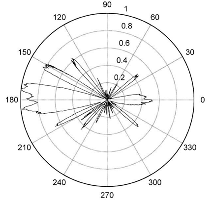
Owing to the unsaturated gray levels, the directivity patterns of ultrasonic scattering field can be displayed by the photoelastic photograph. Two directivity patterns are plotted in Fig.3, where r equals to 8.29 mm and 19.16 mm, respectively. The main lobe and side lobes between 120° and 240° reflect the incident waves and various scattered waves backward, respectively; while the side lobes around ±30° stand for the creep waves propagating along the surface of the cavity.
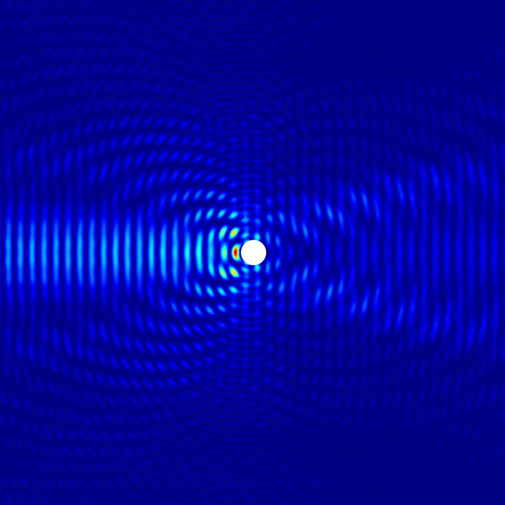
In order to verify the reliability of the dynamic photoelastic experimental results, finite element method (FEM) is also used to calculate the scattering field by the cylindrical cavity (see Fig.4).The differences between photoelastic measurement and numerical calculation show that the dynamic photoelastic method is more reliable directivity patterns which are in close proximity to the practical scattering field.

Fig.1 The schematic diagram of photoelastic system (Image by AN)

Fig. 2 The scattering field of longitudinal waves by a cylindrical (Image by AN)

(a). The directivity patterns at r=8.29mm

(b). The directivity patterns at r=19.16mm
Fig.3. The directivity patterns of scattering field (Image by AN)

Fig. 4 The scattering field simulated by FEM (Image by AN)
References:
AN Zhiwu, JIN Shijie, LIAN Guoxuan, WANG Xiaomin. Investigation on the Directivity of Ultrasonic Scattering Field Using Dynamic Photoelastic Technique. Piezoelectricity, Acoustic Waves, and Device Applications (SPAWDA), 2014 Symposium on, ISBN 978-1-4799-6424-6, IEEE (pp. 408-411, Oct. 30 2014-Nov. 2, 2014, Beijing, China). DOI: 10.1109/SPAWDA.2014.6998611
Contact:
AN Zhiwu
Institute of Acoustics, Chinese Academy of Sciences, 100190 Beijing, China
Email: anzhiwu@mail.ioa.ac.cn


