Good cement bond quality is significant for an oil well to prevent hydraulic communication between zones and to ensure layered exploitation. Conventional sonic logging techniques are limited to the detection region immediately behind the casing, so they can hardly be used to interpret the bonding quality between cement and rock formations.
To develop a cementing evaluation method for the whole annulus, researchers from the Institute of Acoustics, Chinese Academy of Sciences investigated the ultrasonic leaky flexural modes in radially multilayered media through finite-difference modeling. The guided waves were excited and received by pitch-catch transducers arranged in the borehole (Fig. 1). According to the numerical results, two kinds of flexural modes were sensitive to cement debonding at different interfaces, respectively.
For the primary flexural waves that arrived early and propagated all along the casing, the attenuation levels decreased due to the appearance of a fluid-filled channel between the casing and the cement sheath. The acoustic signals arriving later were the secondary flexural modes followed by reflection echoes from the formation. They will be greatly strengthened once a debonding defect appears at the cement-formation boundary. Besides, the arrival time of secondary flexural waves can also be applied to predict the thickness of the cement sheath (see the wavefield snapshots illustrated in Fig. 2). Consequently, it is possible to propose an integrated evaluation for both interfaces of the cement annulus by extracting properties of the primary and secondary flexural waves.
The research will be released in Geophysics (entitled “Ultrasonic Leaky Flexural Waves in Multilayered Media: Cement Bond Detection for Cased Wellbores”, Vol. 79, No. 2, March-April, 2014). This research is supported by the National Natural Science Foundation of China.
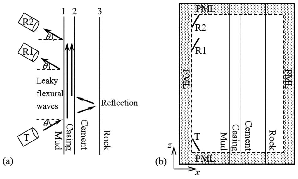
Fig. 1.(a) Pitch-and-catch configuration used to excite and receive leaky flexural waves for the cement bond detection, where the symbol T denotes the transmitter; R1 and R2 represent the two receivers; and numbers one, two, and three denote the first, second, and third interfaces, respectively. (b) A sketch of the 2D model for finite-difference simulations (Image by HE).
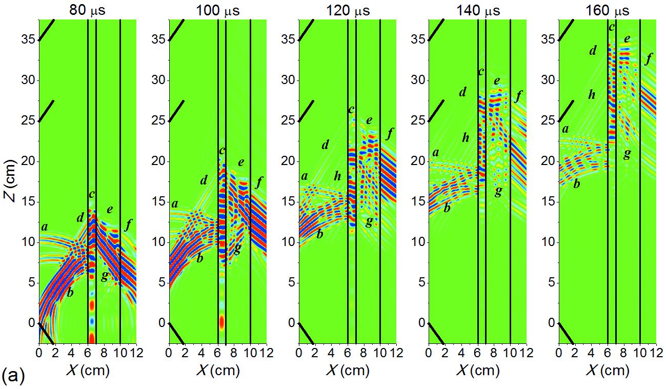
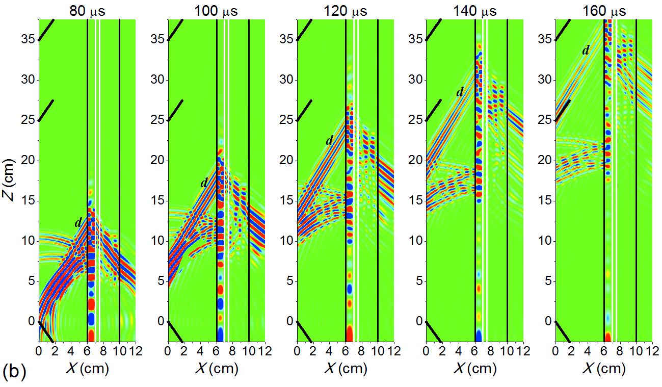
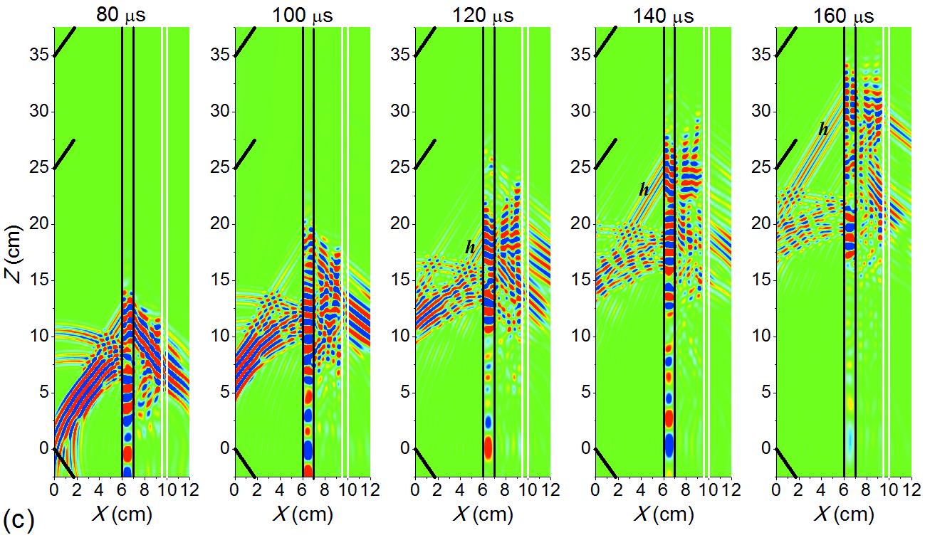
Fig. 2. Simulated time snapshots of normal stress fields at times of 80, 100, 120, 140, and 160 μs, respectively. (a) The cement annulus is well bonded at both interfaces. (b) A 5 mm channel (mud-filled layer) exists at the casing-cement interface. (c) A 5 mm channel appears at the cement-rock interface (Image by HE).
Contact:
HE Xiao
Ultrasonic Physics and Exploration Laboratory, Institute of Acoustics, Chinese Academy of Sciences, Beijing 100190, China
Email: hex@mail.ioa.ac.cn


